Article
Metal Fabrication vs Machining: Processes, Waste, and When to Use Each
Cutlistor Team6 min read
Introduction
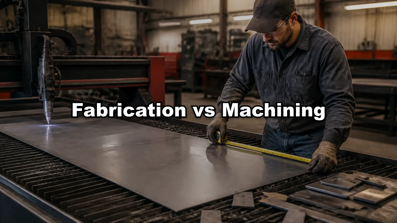
Metal fabrication and machining both produce metal parts, but they start from different stock shapes, use different primary tools, and throw away material in different forms. Fabrication builds from sheet, plate, tube, and angle through cutting, forming, and welding. Machining removes material from solid bar, plate, or castings with mills, lathes, and drills until the final shape appears.
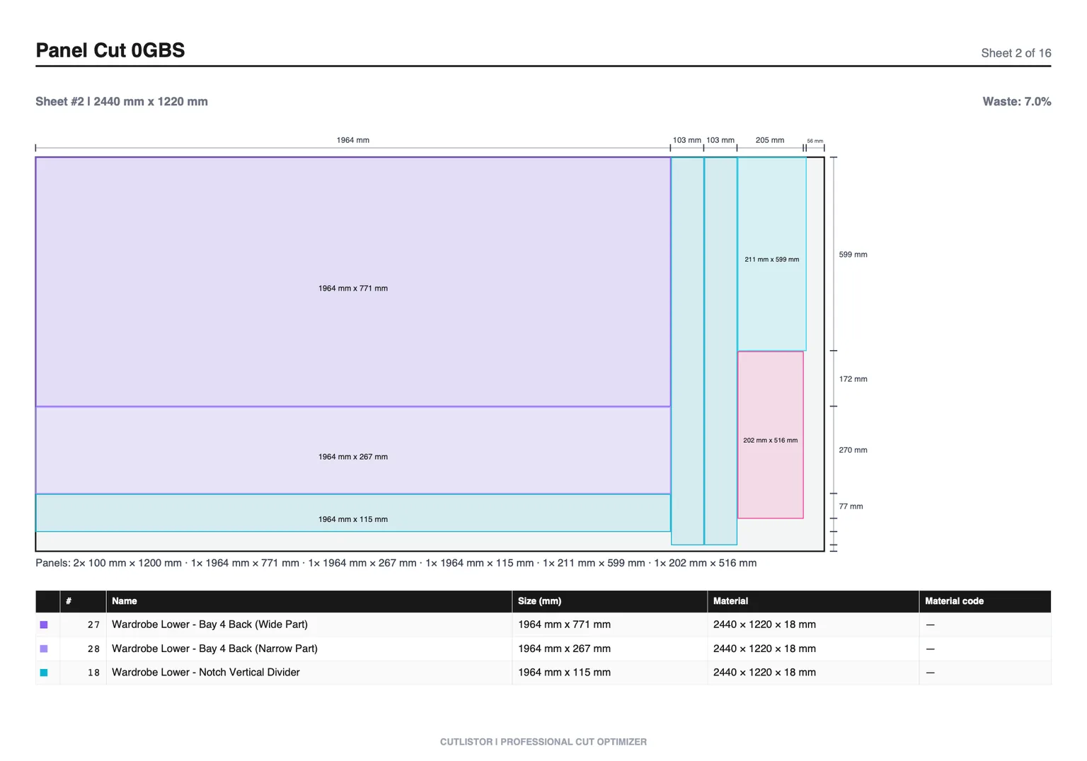
Modern job shops often do both: laser-cut brackets that receive milled pockets, or machined flanges welded to formed shells. This guide compares the two disciplines, shows where they overlap, and explains why cut list optimization applies mainly to fabrication stock cutting while machining waste shows up as chips. For the full fab picture, see metal fabrication.
Definitions: Fabrication vs Machining
Metal fabrication shapes material by cutting flat or linear stock, forming it, and joining pieces. The starting geometry is close to the final envelope: a sheet becomes a box; a tube becomes a frame rail.
Machining is subtractive manufacturing from a solid blank. The starting block is heavier than the finished part. Multi-axis CNC removes material selectively to create holes, pockets, contours, and threads with locational accuracy.
- Fabrication primary stock: sheet, plate, tube, angle, extrusion
- Machining primary stock: bar, plate slug, casting, forging, billet
- Fabrication signature processes: laser/plasma cut, brake bend, weld
- Machining signature processes: milling, turning, drilling, boring, threading
Side-by-Side Comparison
| Factor | Metal fabrication | CNC machining |
|---|---|---|
| Starting stock | Sheet, plate, tube, structural sections | Solid bar, plate block, casting |
| Primary motion | Cut apart, bend, join | Rotate or feed tool against fixed workpiece |
| Typical geometry | Thin shells, frames, brackets, ducts | Pockets, bores, complex 3D surfaces |
| Tolerance sweet spot | ±0.1 to ±0.5 mm on flat features (process dependent) | ±0.01 to ±0.05 mm on locational features |
| Setup driver | Nest layout, bend sequence, weld fixture | Workholding, tool changes, CAM programming |
| Scrap form | Offcuts, skeleton sheet, bar tails | Chips and swarf |
| Economics at volume | Strong on repetitive sheet and tube | Strong when 3D features dominate |
| Material waste planning | 2D/1D nesting, kerf, remnants | Buy-to-size blank; chip recycling |
What Metal Fabrication Includes
Fabrication is a chain of processes, not one machine. Most parts pass through at least cutting and one secondary operation.
Cutting and shearing
Laser, plasma, waterjet, punch, and shear release flats from sheet and plate. Kerf and nest layout determine how much paid-for area becomes parts versus skeleton scrap.
Forming, welding, and assembly
Press brakes form folds; rolls form cylinders; welders join subassemblies. Fabricated assemblies can be large, lightweight structures impossible to hog out of a single billet economically.
What Machining Includes
Machining centers and lathes follow CAM toolpaths to remove material. Five-axis work unifies multiple setups for complex aerospace and mold components. EDM and grinding appear when hard materials or fine finishes demand it.
Machining quotes often start from modeled volume and estimated cycle time, not from a nest on a 4×8 sheet. Stock sizing still matters: buying plate oversize wastes money even if chips are recyclable.
- 3-axis and 5-axis milling for prismatic and sculpted parts
- Turning and mill-turn for rotational symmetry
- Drilling, tapping, boring, and threading as secondary ops
- Workholding and fixture design as hidden cost drivers
- Chip management and coolant maintenance on the floor
Where Fabrication and Machining Overlap
| Scenario | Typical routing |
|---|---|
| Enclosure with bent walls | Fabrication (cut + brake + weld) |
| Impeller or complex 3D surface | Machining or casting + machine finish |
| Bracket with tight bored holes | Fab blank + machining secondary |
| Thick plate structural link | Plasma cut profile + machined bores |
| Tube frame with mitered joints | Linear fab cutting + weld; machine only if pockets needed |
When to Choose Fabrication, Machining, or Both
Choose fabrication when the part is essentially a folded or welded shell, frame, or panel and thickness stays in sheet or plate range. Material utilization and nest yield drive cost.
Choose machining when internal cavities, precise bores, sculpted surfaces, or hard-material features dominate. Cycle time and tooling drive cost.
Choose both when flat pattern efficiency plus localized precision features beats hogging everything from solid.
Fabrication is usually right when
- Walls are thin relative to part size
- The design is a box, channel, duct, or welded frame
- Quantity favors nest-and-repeat on sheet or tube
- Weight savings favor sheet gauge over solid block
Machining is usually right when
- Tight locational tolerances on bores and pockets
- Complex 3D surfaces not achievable on a brake
- Material must stay solid for strength (no weld heat zone)
- Prototype quantity is one and CAM time is acceptable
Material Waste: Nesting vs Chips
Fabrication waste is visible: skeleton sheet on the laser table, bar tails in the bin, odd remnants on the rack. Optimization means packing rectangles on sheets and sequencing cuts on bars with kerf between them. Saving one sheet on a 200-panel job is immediate cash.
Machining waste is granular: chips and swarf collected for recycling. Yield is modeled as buy-to-size versus finished volume, not as a nest diagram. Chip value rarely equals the cost of over-buying a plate slug that is 50 mm thicker than necessary.
Cut list optimization applies mainly to fabrication stock cutting (2D sheet nests and 1D bar sequences). Machining estimators focus on stock size selection, roughing strategy, and scrap credit, not rectangular nesting of dozens of flat blanks.
How Cutlistor Fits Fabrication (Not Machining CAM)
Cutlistor is a browser-based rectangular sheet (2D) nesting and linear (1D) cut list optimizer for tube, bar, and extrusion. It targets fabrication estimators and lead hands who need kerf-aware PDF plans, sheet counts, and stick counts before or alongside laser CAM.
It is not a mill CAM system, not true-shape nesting like SigmaNEST, and not a chip-volume calculator. It works across steel, stainless, and aluminum as geometry-agnostic stock planning.
The free tier draws its line at output, not at effort. Rearranging parts and re-running the nest as many times as you like costs nothing; the daily allowance of 3 is spent only when you export a PDF or open a new project. Sessions hold up to 20 part rows, CSV and XLSX files import up to 5 rows each, and closing the tab clears the work.
- Sheet optimizer: rectangular parts on standard plate sizes with kerf gutters
- Linear optimizer: cut lengths from bars, tubes, angles, extrusions
- CSV/XLSX import, AI plan scan, 3D mesh import on supported tiers
- PDF export for shop floor; DXF export on paid plans for CNC handoff
- Free tier: unlimited edit/re-optimize; daily caps on PDF export and new projects
Stock Guides by Material
Fabrication and machining both consume the same alloys in different forms. Sheet guides help fab quotes; bar and plate sizing for machining still benefits from knowing grade limits and supplier formats.
FAQ
Is fabrication cheaper than machining?
For thin, hollow, or framed geometry, often yes, because you pay for sheet area rather than solid volume. For dense 3D parts with tight features, machining or casting plus finish may win. Quote both routes when the design is ambiguous.
Can Cutlistor optimize CNC milling stock?
Cutlistor optimizes rectangular sheet nests and linear bar cuts. It does not replace mill CAM or model chip volume. Machined parts cut from plate may still use the sheet optimizer when the blank is a simple rectangle purchased from plate stock.
How do hybrid shops plan material?
Run fabrication BOMs through sheet and linear optimizers. Machine shop supervisors size plate slugs and bar from CAM simulations. Keep purchasing lists separate so nest PDFs do not mix with mill setup sheets.
Conclusion
Explore processes, calculators, and software comparisons in the metal fabrication guide. Try the free sheet and linear optimizers on your next fabricated BOM before you buy stock.