Article
Plasma Cutting Explained (2026): How It Works, Kerf, HAZ & When Shops Use It
Cutlistor Team4 min read
Introduction
Plasma cutting sends an electric arc through a constricted gas jet, ionizing the stream into plasma hot enough to melt and blow metal away. Fabricators use it for plate and heavy gauge sheet when laser capital cost is too high or when thick mild steel tolerances do not justify fiber laser hourly rates.
This guide covers plasma physics in plain shop terms, kerf and heat-affected zone (HAZ) expectations, material sweet spots, cost comparisons with laser and waterjet, and how rectangular sheet planning still saves money before parts reach CAM.
How plasma cutting works
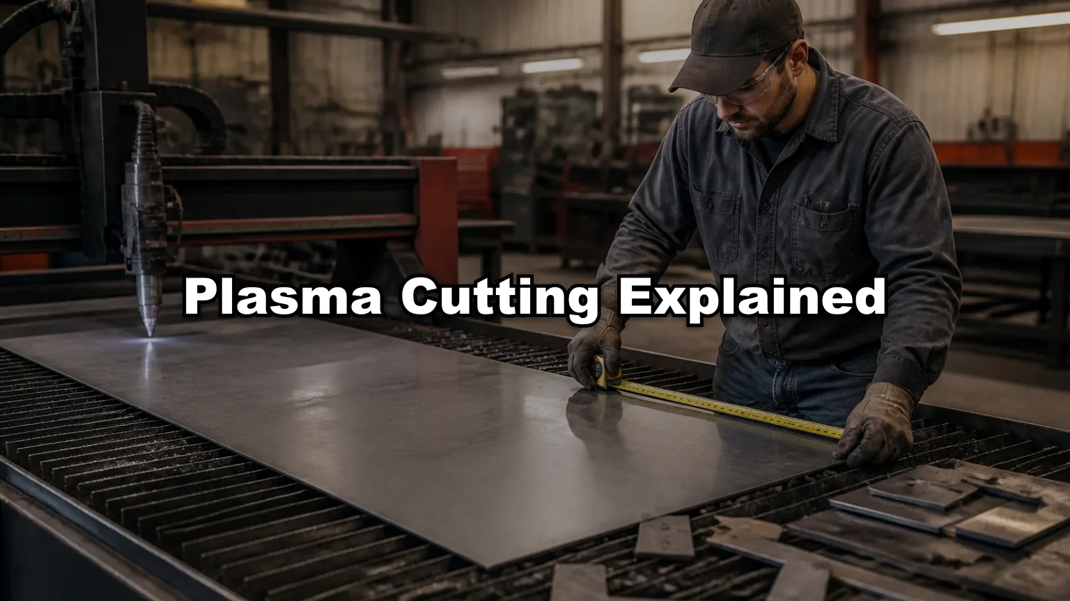
A plasma torch holds a tungsten electrode and a copper nozzle. Compressed air, oxygen, or nitrogen flows between them. The power supply strikes an arc, gas becomes plasma, and the jet exits at high velocity. CNC tables move the torch or the plate to follow programmed contours.
Consumables wear with every cut: electrodes, nozzles, and shields. Amperage, gas choice, and standoff height must match material thickness. Handheld plasma exists for field work; this article focuses on CNC plasma tables common in fab shops.
- Pilot arc: ionizes gas before transferring to the workpiece
- Transfer arc: main cutting current flows plate to torch
- Cut height control: maintains standoff as the plate warps or varies
- Dross: re-solidified slag on the bottom edge when speed or gas is wrong
Mild steel sweet spot
| Material | Typical plasma role | Notes |
|---|---|---|
| Mild steel plate | Primary process 6-50+ mm | Fast, economical, wider tolerances OK |
| Stainless | Secondary to laser on thin sheet | Nitrogen or F5 mixes; more dross risk |
| Aluminum | Mixed; laser often preferred thin | Reflectivity and oxide need care |
| Galvanized | Possible with fume control | Zinc coatings affect edge and extraction |
Kerf, taper, and heat-affected zone
| Process | Typical kerf (mild steel plate) | HAZ |
|---|---|---|
| Precision plasma (thin) | 1.0-1.8 mm | Moderate, wider than laser |
| Conventional plasma (thick) | 2.0-3.5+ mm | Larger HAZ, plan for deburr/grind |
| Fiber laser (reference) | 0.1-0.3 mm | Minimal HAZ on sheet |
| Abrasive waterjet | 0.8-1.2 mm | No thermal HAZ |
Cutlistor uses one kerf number for rectangular sheet nests used in quoting. Plasma CAM adjusts pierce points, kerf compensation on contours, and chain cutting separately. Enter a realistic plasma kerf (often 1.5-2.5 mm for plate estimating) when counting sheets, not laser kerf values.
Thicker plate and machine limits
Table size, amperage, and gantry rigidity cap what a shop can cut. A 125 A precision plasma might cut 20 mm steel cleanly; 400 A systems target 50 mm and above with slower speeds and more taper. Beveling heads can cut weld prep angles in one setup on premium tables.
- Part weight and plate warping: long cuts may need tabbing or staggered sequencing
- Pierce time: thick plate pierces slowly; nest pierces near scrap corners when possible
- Remnant plates: good nesting tracks usable offcuts for future jobs
- Drill-tap secondary ops: plasma holes may need reaming if bolt clearance is tight
Cost vs laser and waterjet
| Factor | Plasma | Fiber laser | Waterjet |
|---|---|---|---|
| Capital cost | Lower | Higher | Moderate to high |
| Running cost | Gas, consumables, power | Power, assist gas | Abrasive, water, pump wear |
| Speed on 12 mm steel | Good | Very good | Slow |
| Speed on 40 mm steel | Good | Possible but costly | Slow but capable |
| Edge tolerance | ±0.5 mm typical, more on thick | ±0.1-0.2 mm common | ±0.1 mm possible |
| Kerf | Wide | Narrow | Medium, no HAZ |
When shops choose plasma
- Structural plate, bases, gussets, and brackets where ±1 mm is acceptable
- Thick mild steel when laser hourly rate or capacity is constrained
- Job shops starting cutting services without laser capital budget
- Parts that will be machined, ground, or welded after cutting anyway
- Long outer profiles where nest density matters more than micro-tolerances
Nesting and cut planning before CAM
Wide kerf makes nesting quality critical on expensive plate. A 2 mm underestimate on kerf across dozens of parts can steal an entire row from the nest. Rectangular optimizers help estimators quote sheet count and weight before true-shape CAM builds torch paths.
Using Cutlistor for plate estimating
Cutlistor runs browser-based rectangular 2D nesting and 1D linear nesting with kerf-aware layouts, PDF cut plans, and paid DXF export. It is not plasma CAM and does not post to your table controller. Use it to answer how many 2500 x 1250 mm plates a BOM needs, then export rectangles to CAM for pierce optimization and chain cutting.
Production nesting software
SigmaNEST and similar platforms handle true-shape plasma nests, common-line cutting, and remnant libraries. Cutlistor fits upstream for quotes and purchase planning; CAM fits downstream for torch motion. See our nesting software comparisons if you are splitting those roles across tools.
Downstream bending and welding
Plasma-cut plate often moves to drilling, welding, or machining rather than press brake bending. When thin plate does go to the brake, remember HAZ and edge taper when placing bend lines. Welded frames may use plasma-cut gussets with MIG for speed; see our welding comparison for fit-up notes.
Conclusion
Plasma cutting is the workhorse for thick mild steel plate: lower machine cost, good speed, wider kerf, and visible HAZ compared with laser. Match kerf in nesting estimates to plasma reality, plan sheet yield before CAM, and route tolerance-critical stainless or thin sheet to laser when the quote allows.